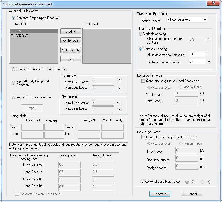
Auto Load Generation: Live Load Screen
There are four options available to generate the longitudinal reactions for live loads:
-
Compute Simple Span Reaction
To use simple span superstructure live load reactions, highlight the live load(s) from the list under Available and click Add. The load will appear in the list under Selected. To view the configuration of the live load, click View.
Substructure always provides the standard live loads according to the CHBDC Specification. However, you can add custom live loads by selecting the Vehicular Loads option from the Libraries menu.
-
Compute Continuous Beam Reactions
If you would like to compute reactions on the pier considering the continuity of the spans and the supports, select this option. To generate live loads using this option, select Live Loads from the list and click Add.
-
Input Computed Reaction
If you have already performed live load analysis of superstructure and already know the live load reactions on the pier, you can specify those using this option. Depending upon the elected pier type, program asks for corresponding input reactions. Program will then try to position this reaction in transverse direction for rest of the live load generation process.
For integral pier, you can specify two sets of four reactions. The left set allows for input of maximum vertical reactions along with associated moment reactions. For truck (in upper row) and for lane (in lower row). The right set of four reactions allows input of maximum moment reaction along with associated vertical reaction, for truck (in upper row) and for lane (in lower row).
To generate a live load by entering an already computed longitudinal reaction, select this option and specify the maximum truck and lane load reactions.
-
Import
CONSPAN/CONBOX Reaction
If you use Precast/Prestressed Girder or CIP RC/PT Girder for superstructure analysis, you can export the results of longitudinal reactions from it on supports to a file and then import those in Substructure for further LL generation.
To import the longitudinal live load reaction from Precast/Prestressed Girder, select this option and click Import.
To import the longitudinal live load reaction from CIP RC/PT Girder, select this option and click Import to open the Import Load Reactions from CIP RC/PT Girder screen.
The Auto Load Generation: Live Load screen also allows you to specify the distribution of loads among bearing lines.
Any value from 0.0 to 1.0 may be specified for a maximum of two bearing lines. When you choose either option 2 or 3 on this dialog, you will also need to specify the factors in which load will be distributed among bearing lines if here are two bering lines. Program allows you input factors for two cases (Case A and Case B) for truck and lane loads.
To generate live loads using transverse positioning, selected the number of lanes to be loaded from the Loaded Lanes list.
Using the live load generation, Substructure first creates live load positions, where live load position is defined by the center of a truck (resultant of two axles) or center of a lane load. After the program has all available live load positions, it selects these positions producing maximum load effect. There are two choices in which you can have live load positions: 1) variable spacing and 2) constant spacing. Variable spacing is where Substructure creates the positions according to a couple of predefined rules (criteria). Constant spacing is where Substructure creates the positions using two inputs provided by the user and assumes even spacing of live load positions. One input is the minimum distance of the nearest truck wheel or tandem load from the curb, and the second is the center-to-center spacing between two consecutive positions (truck and lane). Note that the edge of the lane load is always placed against the face of the curb.
The live loads generated by Substructure do not include the impact factor. The live load generation can be very time-consuming, since the program includes the comprehensive live load positions. Also, the auto live load generation uses simple span analysis for load distribution to the bearings.
This dialog now allows you to optionally generate longitudinal (braking) load and centrifugal load at the same time along with live load. These however, can also be generated separately from respective load case dialogs (i.e. longitudinal and centrifugal force dialogs).
To generate longitudinal forces at the same time along with live load, check the correspondingly option. Then if you would like to generate longitudinal loads for the live loads selected on this dialog, choose auto compute. For this option program will use contributing length to be equal to average of the two adjacent spans. However, you can also switch to manual input and then specify the total live load for one lane to be considered.
To generate centrifugal load at the same time along with live load, check the corresponding option. If you would like to do this generation based on already selected live loads, select the Auto compute option. Then specify the Radius of curve and the design speed. Depending upon the curvature choose to apply the load in the + X direction or - X direction. If you would like to use a different value of total live load, then choose the manual input in this area and specify the total live load to be considered for centrifugal loads for one lane.
Once all required data is entered, click Generate. Substructure will automatically generate all live loads and return to the Loads: Load Data screen.